In the last two posts (here and here), we saw how to drive 64 LEDs (in the form of a 4 digits 7-segments display) with two Arduino wires controlling an I2C bus. But how many LEDs can we control with this architecture? Let's find out. First what we learned. We made groups of 64 LEDs controlled each by an ICM7218a. Then, we used a PCF8574 bus expander to drive the ICM with only two pins. As we saw, we can plug 8 PCF8574 chips in the same bus and 8 additional PCF8574a. So we can have (8 + 8) * 8 = 128 outputs controlled with Arduino's analog 4 and 5. Now, let's see how can we use all this to drive as many LED's as we can. The ICM only checks its inputs when the WRITE pin goes from high to low. So, we can connect the 8 outputs from a PCF to the input pins of the ICM ID0 to ID7. I mean, I can take the outputs of 1 PCF and connect them to the inputs of as many ICM's as I need. With the MODE line, I do the same. As the ICM's only take in account their inputs when WRITE goes low, the only thing we have to do is to connect a different output to each of the ICMs WRITE. To control an ICM I use the common data and MODE lines and it's WRITE pin. If you're lost with the explanation here is a schema of the wiring (for only 3 ICMs).
Conclusion: I only need 1 additional pin to control a single ICM. How many pins do I have left after the use of data and MODE lines? 16 * 8 - 9 = 119 pins. That is, I can control 119 ICMs. As I control 64 LEDs with each ICM, I can drive 119 * 8 = 7,616 independent LED's with two pins! I haven't tested this "invention", but it looks feasible. Doesn't it? And what can we do with the rest of the analog and digital pins?... Maybe we could control some leds!! ;)
In my last post we saw how to use an ICM7218a to control 64 leds. The ICM was driven directly by an Arduino. The problem with this approach is that you need 10 pins. That's a lot.
In this post we'll cover how to reduce the amount of pins needed to just two. With the help of the I2C bus this will be easy.
I2C
I2C is a protocol invented by Phillips that needs the use of only two wires. It allows to communicate all kind of devices that implement the protocol like accelerometers, distance sensors, memory modules, digital potentiometers and many more. One of the devices is the master and is responsible to control the high level communication protocol and the others are slaves that respond to master commands (readings and writings). Arduino implements I2C via the Wire core library. It can act as master or slave, being the coding process very easy. There are several official samples included in the Arduino IDE installation. The two pins used in the Arduino's implementation are analog 4 (SDA) and analog 5 (SCL).
PCF8574
This chip (datasheet) implements I2C in slave mode and offers 8 independent input/output pins. So, you can easily use it to add 8 digital pins to your Arduino. The IC has 3 pins to indicate its slave address. So you can plug 8 units in the same bus to obtain 64 pins. And, what's more, there is another version, the PCF8574A with exactly the same specification except that the address generated are in a different range. So you can add 64 more digital pins. Can you imagine an Arduino with 128 digital pins?
Driving our 7 segments display
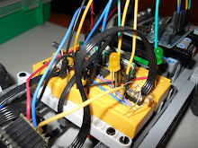
The idea here to reduce the amount of pins needed to control the ICM7218 is to use two PCF8574 that I'll control with two pins. Actually I'm going to use only a PCF8574 in my sample because, as in my previous post, I'm using CODEb decoding. That means that I need at most 7 simultaneous pins. Here you can see a picture of the complete system.
As you can hardly see in the yellow breadboard are still placed the displays and the ICM. But now the wires don't go to the Arduino but to the white one, where the PCF is located. From there, two wires go to analog 4 and 5 at the Arduino. And here a video of the whole "invention" working.
Let's see in detail the wiring used from the PFC8574 to the ICM7218. First I've used two pins for Write (P5) and Mode (P6). Second, 4 pins for SHUTDOWN (P0), DECODE (P1), HEXA/CODE B (P2) and DATA COMING (P4). Finally, 5 pins for the 4 datalines (P0 to P3) plus the digital poins (P4). Note that 4 datalines share the pins with the control pins, as these groups are never used simultaneously. With this wiring the way to control the ICM is simple. As all the data lines are checked when WRITE goes from high to low, to send data you have to set WRITE high in the PCF and then send to this chip the bits you need with WRITE low. At this moment the ICM will respond. At the end of the post you can see the sketch of the video above. In conclusion, adding the I2C capabilities of Arduino with a PCF8574, you can reduce from 10 to 2 the amount of pins needed to drive the ICM7218. And what's more, you can add more PCF modules to drive additional ICM without the need to use any additional pin from Arduino. What's the drawback, apart from having to use an additional chip? Obviuosly, the time. If with the direct driving of the ICM it took 880 microseconds to write the full eight digits, now I need 4788 to do the same. This is 5.5 times more... but I can still make 208 complete writings in a second!
// Pin definition // Actually are pins (P0 to P7) from the PCF8574 #define ID0_PIN B00000001 #define ID1_PIN B00000010 #define ID2_PIN B00000100 #define ID3_PIN B00001000 #define ID7_PIN B00010000
// The 3 address lines are grounded. // Looking at the datasheet this is the address 0x40. // But Wire shifts the address one bit to left in write and read operations, so I have to provide the address shifted to right #define ADDRESS 0x20
// Inclusion of Wire #include <Wire.h>
void setup() { // Setup for Wire Wire.begin();
// Set write to high for the first time sendI2C((byte)NOT_WRITE_PIN);
// A couple of tests // 1- Fill with 00000000 to 99999999 for (int i = 0; i < 10; i++) { write8Digits(i * 11111111); delay(500); }
// 2- Make a full refresh and display the time it takes unsigned long time = micros(); write8Digits((unsigned long)0); // Number to test write8Digits(micros() - time); // Displaying microseconds delay(2000);
}
unsigned long counter = 0; void loop() { // Display an infinite counter write8Digits(counter++); // If you don't wait at least 2 microseconds, the display doesn't have the time to refresh the 8 digits delay(2); }
void sendI2C(byte b) { // Using of I2C in master mode with the device at ADDRESS Wire.beginTransmission(ADDRESS); // Data to send Wire.send(b); // End of communication Wire.endTransmission(); }
void write8Digits(unsigned long num) {
// Control word byte data = MODE_PIN | NOT_SHUTDOWN_PIN | DATA_COMING_PIN; sendI2C(data);
// Write high sendI2C((byte)NOT_WRITE_PIN);
// Sending a digit (will send Write to low) unsigned long digit = num; for (byte i = 0; i < 8; i++){ writeDigit(digit % 10); digit /= 10; } }
void writeDigit(byte b) { // Using CODEB // The digital point allways off (it's inverted) byte data = ID7_PIN; // ID0 to ID3 with the number to display if (B00000001 & b) data |= ID0_PIN; if (B00000010 & b) data |= ID1_PIN; if (B00000100 & b) data |= ID2_PIN; if (B00001000 & b) data |= ID3_PIN;
sendI2C(data);
// Leave Write HIGH for the next writing sendI2C((byte)NOT_WRITE_PIN);