The Arduino software has an official library (LiquidCrystal Library) to control -in a very easy way- that kind of displays. Unfortunately, you need at least 6 pins from the Arduino to control one single display. Once again we'll run out of pins quickly...
So, can we use the same strategy used to control an ICM7218 with only two pins, now with the LCDDisplay? Of course, we can, but this time we'll have to port the original library.
The idea to save (digital) pins is to plug as many PCF8574 chips as you need in a I2C bus, and control it with analog 4 and 5 from Arduino with the Wire library. I recommend to read these two posts (here and here) if you are not familiar with the concept.
The porting was done easily and with good results. I did it without opening the original datasheet, just recoding the Arduino pin working to the use of the PCF8574 connected to the I2C bus. The original library was written in a very clear way.
You can find the new library in my GitHub repository, under Arduino/libraries/PCFCrystal, including some example sketches. Feel free to download and use the library. Remember that the library is provided "as is", without any kind of warranty. (It's been tested only with the two constructors presented below).
Ok, the hard work is done. You only have to use the library! The use of the library is very easy if you know the Liquid Crystal. You only have to use a different syntax for the constructor, include and initialize the Wire library, and the rest of the code is actually the same code you used with Liquid Crystal.
Let's see it in action!
Let's start with an example. I've modified the Hello World example to show the time it takes to print a single character. Below you have a video showing a similar sketch to the one you can find with the code (PCFHelloWorld). It's a bit different as I changed it after the video recording:
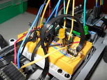
As you can see I'm using an Arduino Pro Mini, but this don't affect to the results.
Now lets see the wiring. There are two versions, for a 4 bits interface and a 8 bits one.
This is the schema for the 4 bits interface. In this case I use a single PCF8574 to control the 6 pins needed.

Now the schema for the 8 bits interface. As you can see in this case I need an extra PCF8574 as I need to control 10 pins.

You can note in the schemas, and see in the video too, that there is a blinking led attached to a free pin of one PCF8574. This is to demonstrate that you can use the unused pins of the PCF8574 for whatever you want without interfering the LCDDisplay.
And now the code. Let's focus in the differences with the original library.
First we need to initilize the Wire library to use I2C.
// Inclusion of Wire
#include <Wire.h>

void setup()
{
// Setup for Wire
Wire.begin();

// TODO: more initialization
}
Then we have to create an PCFCrystal object indicating the pins and address of the PCF(s) used.
For the 4 bits interface this is the code:
byte buffer = 0;
// initialize the library with the numbers of the interface pins
// rs, en, d0, d1, d2, d3, address, buffer
// 4 bits
PCFCrystal lcd(B00100000, B00010000, B00000001, B00000010, B00000100, B00001000, 0x20, &buffer);
As you can see, you need a byte to store the information sent to the PCF8574. Then we call the constructor passing the masks used to access the pins (rs, enable and d0 to d3) plus the byte used to store data and the address of the PCF8574 in the I2C bus. Note that you can use whichever pins you prefer from the PCF8574.
In the case of the 8 bits interface the code is similar except because you need two PCF8574 and consequently, two buffers and addresses. Note that in this case, all the data pins must be in the first PCF, and the control pins (enable and rs) must be in the second one. Here you have the code:
byte buffer = 0;
byte data = 0;
// initialize the library with the numbers of the interface pins
// rs, en, d0, d1, d2, d3, d4, d5, d6, d7, data_address, control_address, data_buffer, control_buffer
PCFCrystal lcd(B00100000, B00010000, B10000000, B01000000, B00100000, B00010000, B00000001, B00000010, B00000100, B00001000, 0x21, 0x20, &data, &buffer);
From that point, the rest of the code is the same as using a regular Liquid Crystal library. Here is the whole sample code with comments:
/*
PCFCrystal Library - Hello World

Demonstrates the use a 16x2 LCD display using the I2C capabilities of Arduino.
This library is a porting of the original LiquidCrystal library, prepared to
control the LCD display via one or two PCF8574.
The LiquidCrystal and PCFLiquidCrystal
libraries work with all LCD displays that are compatible with the
Hitachi HD44780 driver. There are many of them out there, and you
can usually tell them by the 16-pin interface.

This sketch prints "Hello World!" to the LCD
and shows the time and the time consumed to print a single character

The circuit (4 bits interface):
* LCD RS pin to PCF8574 output 5 (pin 10)
* LCD Enable pin to PCF8574 output 4 (pin 9)
* LCD D4 pin to PCF8574 output 0 (pin 4)
* LCD D5 pin to PCF8574 output 1 (pin 5)
* LCD D6 pin to PCF8574 output 2 (pin 6)
* LCD D7 pin to PCF8574 output 3 (pin 7)
* 10K resistor:
* ends to +5V and ground
* wiper to LCD VO pin (pin 3)

Library PCFCrystal created on June 2010
http://ardugonic.blogspot.com

Liquid Crystal:
Library originally added 18 Apr 2008
by David A. Mellis
library modified 5 Jul 2009
by Limor Fried (http://www.ladyada.net)
example added 9 Jul 2009
by Tom Igoe
modified 25 July 2009
by David A. Mellis


http://www.arduino.cc/en/Tutorial/LiquidCrystal
*/

#include <wire.h>

// include the library code:
#include <pcfcrystal.h>

byte buffer = 0;
byte data = 0;
// initialize the library with the numbers of the interface pins
// rs, en, d0, d1, d2, d3, address, buffer
// 4 bits
PCFCrystal lcd(B00100000, B00010000, B00000001, B00000010, B00000100, B00001000, 0x20, &buffer);
// 8 bits
//PCFCrystal lcd(B00100000, B00010000, B10000000, B01000000, B00100000, B00010000, B00000001, B00000010, B00000100, B00001000, 0x21, 0x20, &data, &buffer);

void setup() {
  Wire.begin();

  // set up the LCD's number of rows and columns:
  lcd.begin(16, 2);
  // Print a message to the LCD.
  lcd.print("scnds:loop:micrs");
}

long counter = 0;
int led = HIGH;

void loop() {
  counter++;

  // set the cursor to column 0, line 1
  // (note: line 1 is the second row, since counting begins with 0):
  lcd.setCursor(0, 1);
  // print the number of seconds since reset:
  lcd.print(millis()/1000);
  // print the number of loops since reset
  lcd.print(":");
  lcd.print(counter);
  // print the time to print 1 char
  long mics = micros();
  lcd.print(":");
  lcd.print(micros() - mics );

  if (counter % 27 == 0) {
    if (led == LOW) {
      buffer = buffer | B01000000;
      led = HIGH;
    }
    else {
      buffer = buffer & ~B01000000;
      led = LOW;
    }

    Wire.beginTransmission(0x20);
    Wire.send(buffer);
    Wire.endTransmission();
  }
}
Perfomance
Obviously the drawback of using this approach is that you spend more time to make the operations. But how much more? I don't know, but as an estimation, this sample sketch prints in the display the time spent to write a single character. I've tested the sample with both LiquidCrystal and PCFCrystal libraries in 4 and 8 bits interface and this is the result:
- LiquidCrystal, 8 bits: 208 microseconds.
- LiquidCrystal, 4 bits: 324 microseconds.
- PCFCrystal, 8 bits: 1196 microseconds.
- PCFCrystal, 4 bits: 1664 microseconds.
This is only an orientation. When you write strings it's supposed to take comparatively less time difference. Anyway it's clear that the saving in pins is payed with a decrease of performance. Is up to you to decide witch solution is better for your project.