In the last two posts (here and here), we saw how to drive 64 LEDs (in the form of a 4 digits 7-segments display) with two Arduino wires controlling an I2C bus. But how many LEDs can we control with this architecture? Let's find out. First what we learned. We made groups of 64 LEDs controlled each by an ICM7218a. Then, we used a PCF8574 bus expander to drive the ICM with only two pins. As we saw, we can plug 8 PCF8574 chips in the same bus and 8 additional PCF8574a. So we can have (8 + 8) * 8 = 128 outputs controlled with Arduino's analog 4 and 5. Now, let's see how can we use all this to drive as many LED's as we can. The ICM only checks its inputs when the WRITE pin goes from high to low. So, we can connect the 8 outputs from a PCF to the input pins of the ICM ID0 to ID7. I mean, I can take the outputs of 1 PCF and connect them to the inputs of as many ICM's as I need. With the MODE line, I do the same. As the ICM's only take in account their inputs when WRITE goes low, the only thing we have to do is to connect a different output to each of the ICMs WRITE. To control an ICM I use the common data and MODE lines and it's WRITE pin. If you're lost with the explanation here is a schema of the wiring (for only 3 ICMs).
Conclusion: I only need 1 additional pin to control a single ICM. How many pins do I have left after the use of data and MODE lines? 16 * 8 - 9 = 119 pins. That is, I can control 119 ICMs. As I control 64 LEDs with each ICM, I can drive 119 * 8 = 7,616 independent LED's with two pins! I haven't tested this "invention", but it looks feasible. Doesn't it? And what can we do with the rest of the analog and digital pins?... Maybe we could control some leds!! ;)
In my last post we saw how to use an ICM7218a to control 64 leds. The ICM was driven directly by an Arduino. The problem with this approach is that you need 10 pins. That's a lot.
In this post we'll cover how to reduce the amount of pins needed to just two. With the help of the I2C bus this will be easy.
I2C
I2C is a protocol invented by Phillips that needs the use of only two wires. It allows to communicate all kind of devices that implement the protocol like accelerometers, distance sensors, memory modules, digital potentiometers and many more. One of the devices is the master and is responsible to control the high level communication protocol and the others are slaves that respond to master commands (readings and writings). Arduino implements I2C via the Wire core library. It can act as master or slave, being the coding process very easy. There are several official samples included in the Arduino IDE installation. The two pins used in the Arduino's implementation are analog 4 (SDA) and analog 5 (SCL).
PCF8574
This chip (datasheet) implements I2C in slave mode and offers 8 independent input/output pins. So, you can easily use it to add 8 digital pins to your Arduino. The IC has 3 pins to indicate its slave address. So you can plug 8 units in the same bus to obtain 64 pins. And, what's more, there is another version, the PCF8574A with exactly the same specification except that the address generated are in a different range. So you can add 64 more digital pins. Can you imagine an Arduino with 128 digital pins?
Driving our 7 segments display
The idea here to reduce the amount of pins needed to control the ICM7218 is to use two PCF8574 that I'll control with two pins. Actually I'm going to use only a PCF8574 in my sample because, as in my previous post, I'm using CODEb decoding. That means that I need at most 7 simultaneous pins. Here you can see a picture of the complete system.
As you can hardly see in the yellow breadboard are still placed the displays and the ICM. But now the wires don't go to the Arduino but to the white one, where the PCF is located. From there, two wires go to analog 4 and 5 at the Arduino. And here a video of the whole "invention" working.
Let's see in detail the wiring used from the PFC8574 to the ICM7218. First I've used two pins for Write (P5) and Mode (P6). Second, 4 pins for SHUTDOWN (P0), DECODE (P1), HEXA/CODE B (P2) and DATA COMING (P4). Finally, 5 pins for the 4 datalines (P0 to P3) plus the digital poins (P4). Note that 4 datalines share the pins with the control pins, as these groups are never used simultaneously. With this wiring the way to control the ICM is simple. As all the data lines are checked when WRITE goes from high to low, to send data you have to set WRITE high in the PCF and then send to this chip the bits you need with WRITE low. At this moment the ICM will respond. At the end of the post you can see the sketch of the video above. In conclusion, adding the I2C capabilities of Arduino with a PCF8574, you can reduce from 10 to 2 the amount of pins needed to drive the ICM7218. And what's more, you can add more PCF modules to drive additional ICM without the need to use any additional pin from Arduino. What's the drawback, apart from having to use an additional chip? Obviuosly, the time. If with the direct driving of the ICM it took 880 microseconds to write the full eight digits, now I need 4788 to do the same. This is 5.5 times more... but I can still make 208 complete writings in a second!
// Pin definition // Actually are pins (P0 to P7) from the PCF8574 #define ID0_PIN B00000001 #define ID1_PIN B00000010 #define ID2_PIN B00000100 #define ID3_PIN B00001000 #define ID7_PIN B00010000
// The 3 address lines are grounded. // Looking at the datasheet this is the address 0x40. // But Wire shifts the address one bit to left in write and read operations, so I have to provide the address shifted to right #define ADDRESS 0x20
// Inclusion of Wire #include <Wire.h>
void setup() { // Setup for Wire Wire.begin();
// Set write to high for the first time sendI2C((byte)NOT_WRITE_PIN);
// A couple of tests // 1- Fill with 00000000 to 99999999 for (int i = 0; i < 10; i++) { write8Digits(i * 11111111); delay(500); }
// 2- Make a full refresh and display the time it takes unsigned long time = micros(); write8Digits((unsigned long)0); // Number to test write8Digits(micros() - time); // Displaying microseconds delay(2000);
}
unsigned long counter = 0; void loop() { // Display an infinite counter write8Digits(counter++); // If you don't wait at least 2 microseconds, the display doesn't have the time to refresh the 8 digits delay(2); }
void sendI2C(byte b) { // Using of I2C in master mode with the device at ADDRESS Wire.beginTransmission(ADDRESS); // Data to send Wire.send(b); // End of communication Wire.endTransmission(); }
void write8Digits(unsigned long num) {
// Control word byte data = MODE_PIN | NOT_SHUTDOWN_PIN | DATA_COMING_PIN; sendI2C(data);
// Write high sendI2C((byte)NOT_WRITE_PIN);
// Sending a digit (will send Write to low) unsigned long digit = num; for (byte i = 0; i < 8; i++){ writeDigit(digit % 10); digit /= 10; } }
void writeDigit(byte b) { // Using CODEB // The digital point allways off (it's inverted) byte data = ID7_PIN; // ID0 to ID3 with the number to display if (B00000001 & b) data |= ID0_PIN; if (B00000010 & b) data |= ID1_PIN; if (B00000100 & b) data |= ID2_PIN; if (B00001000 & b) data |= ID3_PIN;
sendI2C(data);
// Leave Write HIGH for the next writing sendI2C((byte)NOT_WRITE_PIN);
For my next project (a four-lanes Arduino controlled lap counter for my home slot car track) I need several 7-segment displays. Some time ago I found this really cheap 4-Digit 7-Segment Display at Sparkfun.
The problem was that this display is common anode and I didn't know any led driver suitable for common anode displays. The famous MAX7219 is only suitable for common cathode displays. Fortunately in the comments of the Saparkfun's page, the user IsotopeJ commented the existence ICM7218 chip. I got one at my local store and I've managed to put all working. This has been a quick (beside the resulting mess of wires), easy and straightforward process. This is the result:
The usage of the ICM7218A is perfectly explained in its datasheet.
This single chip allows to control up to 8 digits (or 64 leds) using 8 data lines and 2 control lines. So I can control two Sparkfun displays with a single chip and, what's really interesting, once the data is stored in the IC, leaving the Arduino totally free to do other tasks.
There are two drawbacks for using this chip.
The first one is that you can't access to random leds or digits directly. If you want to change a single led, you have to send again the state for the 64 leds plus a 8 bits control word. This is, you have to send allways nine 8-bits words. This might be a problem if your application is time aware.
The second one is that you have to use ¡10 pins! and there's not an "out of the box" way to chain several chips if you have to control more than 8 digits. This can be a problem for our poor Arduino and its 14+6 pins! Fortunately this can be solved with one more chip, as I'll explain in my next post.
So, lets see how to use the ICM.
Firstly the wiring. The ICM7218 uses 16 data lines to control 8 groups (DIGIT1 to DIGIT8) of leds (SEG a to SEG f and D.P.) each. If you're using a module like the one referred from Sparkfun, the wiring is trivial to control the multiplexed digits, leaving uncontrolled the colon and apostrophe. If you're trying to control 64 separate leds you have to:
Group them in groups of 8. Each group will be a digit.
Wire all the anodes of each group to a DIGIT output.
Take one led from every group and wire them together to the SEG a.
Repeat 3 for the other leds through SEG b to SEG e and D.P.
And don't forget to power the IC. In this sample you can see that I've used an external 9v battery and an LM7805 (it's below the wires at the right edge of the breadboard) to stabilize the power to 5 volts.
Secondly the logic to control the IC from Arduino. You have to use the ID0 to ID7 inputs plus the pins WRITE and MODE. The most important pin is WRITE. When the pin goes from high to low, the IC interprets the other inputs. For the rest of the time all the inputs are ignored.
So, choose a pin for every input and use this logic to refresh the state of the whole group of leds:
Turn WRITE high.
Prepare the control word:
Set MODE high.
Set ID4 (SHUTDOWN) high.
Set ID5 (DECODE) low if you want to control the leds directly or LOW if you want the input to be decoded as Code B or Hexadecimal. In this case put ID6 (HEXA/CODE B) high for Code B or low for Hexa.
Set ID7 (DATA COMING) high.
Send the control word by setting WRITE to LOW.
Set MODE to LOW.
For every digit send the data (starting at digit 1):
Set WRITE to high.
Put the data in the 8 inputs if you're not decoding or in ID0 to ID3 plus ID7 for the digital point if you are decoding.
Set WRITE to low to send the digit.
Note that you must send the 8 digits. Additionally note that when you send the control word, the display will go blank until the 8 digits are received. This can dim the display if you refresh it very quick.
And that's all. Nice and easy.
You can use this little sketch to test the chips and as a base for your own developments. At the beginning of the sketch you can see the pins used.
With this sketch you spend about 880 microseconds to update the state of the 64 leds.
// Note that these pins are the same as ID4-ID7 #define NOT_SHUTDOWN_PIN 8 #define NOT_DECODE_PIN 9 #define NOT_CODE_B_PIN 10 #define DATA_COMING_PIN 11
// A couple of tests // 1- Fill with 00000000 to 99999999 for (int i = 0; i < 10; i++) { write8Digits(i * 1111); delay(2000); }
// 2- Make a full refresh and display the time it takes unsigned long time = micros(); write8Digits(0); // Number to test write8Digits(micros() - time); // Displaying microseconds delay(1000); }
unsigned long counter = 0;
void loop() { // Display an infinite counter write8Digits(counter++); delay(2); // If you don't wait at least 2 microseconds, the display doesn't have the time to refresh the 8 digits }
// Function to write the 8 digits // Uses Code B encoding in the ICM void write8Digits(unsigned long num) { // Control Mode digitalWrite(NOT_WRITE_PIN, HIGH); digitalWrite(MODE_PIN, HIGH);
// Setup control word digitalWrite(NOT_SHUTDOWN_PIN, HIGH); // Normal mode digitalWrite(NOT_DECODE_PIN, LOW); // Decode mode digitalWrite(NOT_CODE_B_PIN, LOW); // CodeB mode digitalWrite(DATA_COMING_PIN, HIGH); // The data to display will follow
// Write the control word digitalWrite(NOT_WRITE_PIN, LOW); digitalWrite(NOT_WRITE_PIN, HIGH);
// Write digits, so mode to low digitalWrite(MODE_PIN, LOW);
// Send the 8 digits, starting by the least significant unsigned long digit = num; for (byte i = 0; i < 8; i++){ writeDigit(digit % 10); digit /= 10; } }
void writeDigit(byte b) { // I'm using CodeB, so I only need the 4 least significant pins digitalWrite(ID0_PIN, B00000001 & b); digitalWrite(ID1_PIN, B00000010 & b); digitalWrite(ID2_PIN, B00000100 & b); digitalWrite(ID3_PIN, B00001000 & b); // Digital point allways low (Note that it's inverted by the ICM) digitalWrite(ID7_PIN, HIGH);
// Write the digit digitalWrite(NOT_WRITE_PIN, LOW); digitalWrite(NOT_WRITE_PIN, HIGH); }
Ongoing button monitor to fail if a button is pressed when it's not the user's turn.
Time out on excessive delay in the user's turn.
A 7-segments display to show animations, count-down time and final score controlled by a 595 shift register.
A servo to show the progress.
Two user controllers: my generic control panel and a Lego Technic one.
And all controlled with an Arduino, of course.
Do you want to see it working? Watch the video.
If we all know the world is plenty of Simon games, why did I make another Simon? Because it's a good demonstration for my PScheduller library, the real motivation of this post, and because my children have fun with it.
PScheduller
Let's introduce PScheduller. PScheduller is a library for Arduino developed with two goals in mind:
To have a simple way to run several tasks simultaniously. This is, a kind of multithreading.
To implement a state machin (FSM) that allows the programmer to focus on what really matters depending on the state of the program.
PScheduller is a library mainly written in C++. You can download it from my GitHub repository. There you'll find the directory PScheduller that you have to put under hardware/libraries/ at your arduino's installation directory. You'll find too the full code of Susi (named PSimon) that you have to put in your Arduino projects directory.
In future posts I'll describe PScheduller and its usage, and the code of PSimon. If you download and open PSimon, don't get scary. PSimon it's a relatively complex program due to the number of components it controls. With simpler programs, the code is really clear and straightforward.
The lego version
The version of the video avobe uses my generic control panel (you'll have a future post on it too). I constructed a Lego Technic panel for Susi to be more useful for my children. They like to play with it!
You can see a video of this second version in action:
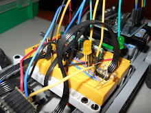
In this version I've substituted the momentary push buttons of the generic panel by four limit switches. They are actually well integrated in the Lego structure and produce the "click" that you can heard in the video each time the user presses a color. Look at the picture below.
By the way, this was my first "real" project combining electronics with a Lego structure. And I learned an important lesson: you have to plan what you want to do before doing it. I just started to construct the structure, to place components and to solder long wires to avoid problems when I plug the terminals in the Arduino or a breadboard. But when it was time to plug it all, I discovered that it was dificult to have a comfortable layout. In fact you can see in the video how the 7-segments is in a strange position...
Summing up
Ok, it's enough for today. I don't like long posts.
To complement this post I'll comment in future posts:
In depth explanation of PScheduller with some easy samples.
In depth explanation of Susi (PSimon) code as a sample of a more complex program using PScheduller.
An introduction to my generic controller. It's really useful.
If you have any preference or suggestion about more topics regarding this post, please, leave a comment and I'll try to respond (the comments are moderated just to avoid spammers).
In this blog I'll post about my two current hobbys: Arduino (electronics) and Lego, specially Lego Technic. I'll document here my progress in merging this two technologies to make amazing -I hope- projects.
Get fun!
Disclaimer. I apologize for my poor english. Although my mother tongues are spanish and catalan, I prefere to write in english to reach a wider audience who can enrich this blog with its comments. Of course, you are welcome to correct my writings ;)