The problem was that this display is common anode and I didn't know any led driver suitable for common anode displays. The famous MAX7219 is only suitable for common cathode displays. Fortunately in the comments of the Saparkfun's page, the user IsotopeJ commented the existence ICM7218 chip. I got one at my local store and I've managed to put all working. This has been a quick (beside the resulting mess of wires), easy and straightforward process. This is the result:


The usage of the ICM7218A is perfectly explained in its datasheet.
This single chip allows to control up to 8 digits (or 64 leds) using 8 data lines and 2 control lines. So I can control two Sparkfun displays with a single chip and, what's really interesting, once the data is stored in the IC, leaving the Arduino totally free to do other tasks.
There are two drawbacks for using this chip.
- The first one is that you can't access to random leds or digits directly. If you want to change a single led, you have to send again the state for the 64 leds plus a 8 bits control word. This is, you have to send allways nine 8-bits words. This might be a problem if your application is time aware.
- The second one is that you have to use ¡10 pins! and there's not an "out of the box" way to chain several chips if you have to control more than 8 digits. This can be a problem for our poor Arduino and its 14+6 pins! Fortunately this can be solved with one more chip, as I'll explain in my next post.
So, lets see how to use the ICM.
Firstly the wiring. The ICM7218 uses 16 data lines to control 8 groups (DIGIT1 to DIGIT8) of leds (SEG a to SEG f and D.P.) each. If you're using a module like the one referred from Sparkfun, the wiring is trivial to control the multiplexed digits, leaving uncontrolled the colon and apostrophe. If you're trying to control 64 separate leds you have to:
- Group them in groups of 8. Each group will be a digit.
- Wire all the anodes of each group to a DIGIT output.
- Take one led from every group and wire them together to the SEG a.
- Repeat 3 for the other leds through SEG b to SEG e and D.P.
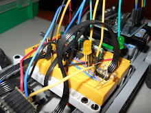
And don't forget to power the IC. In this sample you can see that I've used an external 9v battery and an LM7805 (it's below the wires at the right edge of the breadboard) to stabilize the power to 5 volts.
Secondly the logic to control the IC from Arduino. You have to use the ID0 to ID7 inputs plus the pins WRITE and MODE. The most important pin is WRITE. When the pin goes from high to low, the IC interprets the other inputs. For the rest of the time all the inputs are ignored.
So, choose a pin for every input and use this logic to refresh the state of the whole group of leds:
- Turn WRITE high.
- Prepare the control word:
- Set MODE high.
- Set ID4 (SHUTDOWN) high.
- Set ID5 (DECODE) low if you want to control the leds directly or LOW if you want the input to be decoded as Code B or Hexadecimal. In this case put ID6 (HEXA/CODE B) high for Code B or low for Hexa.
- Set ID7 (DATA COMING) high.
- Send the control word by setting WRITE to LOW.
- Set MODE to LOW.
- For every digit send the data (starting at digit 1):
- Set WRITE to high.
- Put the data in the 8 inputs if you're not decoding or in ID0 to ID3 plus ID7 for the digital point if you are decoding.
- Set WRITE to low to send the digit.
Note that you must send the 8 digits. Additionally note that when you send the control word, the display will go blank until the 8 digits are received. This can dim the display if you refresh it very quick.
And that's all. Nice and easy.
You can use this little sketch to test the chips and as a base for your own developments. At the beginning of the sketch you can see the pins used.
With this sketch you spend about 880 microseconds to update the state of the 64 leds.
// Pin usage
#define ID0_PIN 2
#define ID1_PIN 3
#define ID2_PIN 4
#define ID3_PIN 5
#define ID4_PIN 8
#define ID5_PIN 9
#define ID6_PIN 10
#define ID7_PIN 11

#define NOT_WRITE_PIN 6
#define MODE_PIN 7

// Note that these pins are the same as ID4-ID7
#define NOT_SHUTDOWN_PIN 8
#define NOT_DECODE_PIN 9
#define NOT_CODE_B_PIN 10
#define DATA_COMING_PIN 11

void setup()
{
 // All pins are output
 pinMode(ID0_PIN, OUTPUT);
 pinMode(ID1_PIN, OUTPUT);
 pinMode(ID2_PIN, OUTPUT);
 pinMode(ID3_PIN, OUTPUT);
 pinMode(ID4_PIN, OUTPUT);
 pinMode(ID5_PIN, OUTPUT);
 pinMode(ID6_PIN, OUTPUT);
 pinMode(ID7_PIN, OUTPUT);
 pinMode(NOT_WRITE_PIN, OUTPUT);
 pinMode(MODE_PIN, OUTPUT);

 // A couple of tests
 // 1- Fill with 00000000 to 99999999
 for (int i = 0; i < 10; i++) {
   write8Digits(i * 1111);
   delay(2000);
 }

 // 2- Make a full refresh and display the time it takes
 unsigned long time = micros();
 write8Digits(0); // Number to test
 write8Digits(micros() - time); // Displaying microseconds
 delay(1000);
}

unsigned long counter = 0;

void loop()
{
 // Display an infinite counter
 write8Digits(counter++);
 delay(2); // If you don't wait at least 2 microseconds, the display doesn't have the time to refresh the 8 digits
}

// Function to write the 8 digits
// Uses Code B encoding in the ICM
void write8Digits(unsigned long num)
{
 // Control Mode
 digitalWrite(NOT_WRITE_PIN, HIGH);
 digitalWrite(MODE_PIN, HIGH);

 // Setup control word
 digitalWrite(NOT_SHUTDOWN_PIN, HIGH);  // Normal mode
 digitalWrite(NOT_DECODE_PIN, LOW); // Decode mode
 digitalWrite(NOT_CODE_B_PIN, LOW); // CodeB mode
 digitalWrite(DATA_COMING_PIN, HIGH); // The data to display will follow

 // Write the control word
 digitalWrite(NOT_WRITE_PIN, LOW);
 digitalWrite(NOT_WRITE_PIN, HIGH);

 // Write digits, so mode to low
 digitalWrite(MODE_PIN, LOW);

 // Send the 8 digits, starting by the least significant
 unsigned long digit = num;
 for (byte i = 0; i < 8; i++){
   writeDigit(digit % 10);
   digit /= 10;
 }
}

void writeDigit(byte b)
{
 // I'm using CodeB, so I only need the 4 least significant pins
 digitalWrite(ID0_PIN, B00000001 & b);
 digitalWrite(ID1_PIN, B00000010 & b);
 digitalWrite(ID2_PIN, B00000100 & b);
 digitalWrite(ID3_PIN, B00001000 & b);
 // Digital point allways low (Note that it's inverted by the ICM)
 digitalWrite(ID7_PIN, HIGH);

 // Write the digit
 digitalWrite(NOT_WRITE_PIN, LOW);
 digitalWrite(NOT_WRITE_PIN, HIGH);
}
Hi,
ReplyDeletesory for my bad english,
i used pcf 8574 with arduino mega I would know if I can write pin/pin could you help me please
oliviercouteau@francelec89.com
Hello,
ReplyDeleteI'm not sure if I undertand well your question, but all the code in this blog was produced for the Arduino Duemillanove, so it has to be compatible with Arduino Mega.
Hi. Thanks for this post! I'm actually pulling my hair off trying to use a LED matrix (common cathode) with an ICM7218, I can't get it to work. This bitch is driving me crazy!
ReplyDeleteI wired the chip using the datasheet exactly as mentioned above. Could you please help?
Hi,
ReplyDeletefeel free to make any concrete question you have. Otherwise I don't know how can I help you.
good night, I bought one icm7228cipi and i want getting it to work, and needed help, I think the wirings must be different and even the code is also different.
ReplyDeleteMuch appreciate the help.
Best regards
Hi,
ReplyDeleteif you give me more details maybe I can help you.
Regards.
hi Ardugo, i need wiring instructions and example code (Arduino sketch) to chip ICM7228CIPI
ReplyDeleteBest regards
It works, but my digits are not very bright.
ReplyDeleteCan you tell me more about the 7805 and how to use it, and wire it up?
I tried using one of these with a 9V power supply.
http://store.tautic.com/dual-output-breadboard-power-supply.html
But I think it only supplies 300mA (which may be all the 7218 can handle)
Deadbird, I also purchased the common cathode version which is 7218B, with common cathode 7 segment LED's. I have spent two days trying to get it to work and all I get is 8's. Have you had any luck getting yours to work? If so, how? I wonder if something needs to be different in the code or wiring with a common cathode?
ReplyDeleteWhat is the blue component on the bottom right of the bread board image? I gather it is some sort of capacitor? why do you need it and what is it's capacitance? thank you
ReplyDeleteHi,
Deletethis is stated in the datasheet of the 7218:
"Supply Capacitor
A 0.1μF plus a 47μF capacitor is recommended between VDD and VSS to bypass display multiplexed noise."
thank you! this is my first foray into arduino and i've only done very minor digital electronics work before so your posts have been fantastic as i'm trying to build a similar project (an 8 digit chess timer)
ReplyDeleteOne more question, home did you avoid using any resistors for the display? my understanding is that arduino pins put out 5.0 volts and these displays need 2.1 volts, wouldn't you need a resistor to avoid burning them out? or do you have resistors that i just can't see here? thanks again!
ReplyDeleteHi,
Deletethe display is not connected directly to the arduino but through the ICM7218, so no resistors needed.